How to extend the life of your motor bearings
Electric motors play a vital role in our everyday lives – where we live, work and play. Simply put, they make almost everything that moves, move. Nearly 70 percent of electricity consumed by industry is used by electric motor systems.1
 Roughly 75 percent of the industrial motors in operation are used to run pumps, fans and compressors, a category of machinery that is highly susceptible to major efficiency improvements2. These applications often operate at constant speed, all the time, even when not needed. This constant operation wastes energy and produces unnecessary CO2 emissions, but by controlling a motor’s speed, we can reduce power consumption, saving energy and reducing environmental impact.
One way to control a motor’s speed is through the use of a variable speed drive (VSD), a device that regulates an electric motor’s rotational speed by varying the frequency and voltage supplied to the motor. By controlling a motor’s speed, a drive can reduce power consumption (for example, reducing rotating equipment speed by 20 percent can reduce input power requirements by approximately 50 percent3) and provide a considerable improvement in process control and significant cost of operation savings over the life of the motor.
 As useful as VSDs are for saving energy in many applications, they can cause premature motor failure if not properly grounded. While there are many different causes of electric motor failures, the most common issue when using a drive is bearing failure caused by common mode voltage.
Damage caused by common mode voltage
In a three-phase AC system, common mode voltage can be defined as the imbalance present between the three phases created by the pulse width modulated power of the drive, or the voltage difference between the power source ground and the neutral point of the three-phase load. This fluctuating common mode voltage electrostatically induces voltage on the motor’s shaft, and this shaft voltage can discharge through the windings or through the bearings. Modern engineering designs, phase insulation and inverter spike-resistant wire can help protect the windings; however, when the rotor sees a buildup of voltage spikes, the current seeks the path of least resistance to ground. In the case of an electric motor, this path runs directly through the bearings.
Since motor bearings utilize grease for lubrication, the oil in the grease forms a film that acts as a dielectric, which means it can transmit the electric forces without conduction. Over time though, this dielectric breaks down. Without the insulation properties of the grease, the shaft voltage will discharge through the bearings, then through the motor’s housing, to achieve electrical earth ground. This movement of electrical current causes arcing in the bearings, commonly referred to as electrical discharge machining (EDM). As this continual arcing occurs over time, the surface areas in the bearing race become brittle, and tiny pieces of metal can break off inside the bearing. Eventually, the damaged material works its way between the bearing’s balls and races, causing a grinding effect, which can produce micron-sized pitting, called frosting, or washboard-like ridges in the bearing raceway, called fluting.
Some motors can continue to run as the damage gets progressively worse, without any noticeable issues. The first sign of bearing damage is usually an audible noise, due to the bearing balls traveling over the pitted and frosted areas. But by the time this noise occurs, the damage has usually become substantial enough that failure is imminent.

Grounded in prevention
Industrial applications typically don’t experience these bearing difficulties on variable speed motors, but in some installations, such as commercial buildings and airport baggage handling, robust grounding is not always available. In these instances, another method must be used to divert this current away from the bearings. The most common solution is to add a shaft grounding device to one end of the motor shaft, especially in applications where common mode voltage can be more prevalent. A shaft ground is essentially a means to connect the turning rotor of the motor to earth ground via the frame of the motor. Adding a shaft grounding device to the motor prior to installation (or buying a motor with one pre-installed) can be a small price to pay when compared to the price tag of maintenance costs associated with bearing replacement, not to mention the high costs of downtime in a facility.
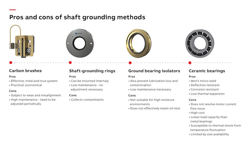
There are several common types of shaft grounding devices in the industry today, such as carbon brushes, ring-style fiber brushes and grounding bearing isolators, and other methods of protecting the bearings are also available.
Carbon brushes have been in use for more than 100 years and are similar to the carbon brushes used on DC motor commutators. Grounding brushes provide the electrical connection between the rotating and stationary portions of the motor’s electrical circuit and take the current from the rotor to ground so that the charge does not build up on the rotor to the point where it discharges through the bearings. Grounding brushes offer a practical and economical means to provide a low-impedance path to ground, especially for larger frame motors; however, they are not without their drawbacks. As with DC motors, the brushes are subject to wear because of the mechanical contact with the shaft, and, regardless of the design of the brush holder, the assembly must be periodically inspected to assure proper contact between the brushes and the shaft.
Shaft-grounding rings work like a carbon brush, but they contain multiple strands of electrically conductive fibers arranged inside a ring around the shaft. The outside of the ring, which is typically mounted to the endplate of the motor, remains stationary, while the brushes ride on the surface of the motor shaft, directing the current through the brushes and safely to ground. Shaft-grounding rings can be mounted inside the motor, allowing them to be used on washdown duty and dirty duty motors. No shaft grounding method is perfect, however, and grounding rings mounted externally tend to collect contaminants on their bristles, which may reduce their effectiveness.
Grounding bearing isolators combine two technologies: a two-part, non-contact isolation shield that uses a labyrinth design to prevent ingress of contaminants and a metallic rotor and isolated conductive filament ring to divert shaft currents away from the bearings. Since these devices also prevent lubricant loss and contamination, they replace standard bearing seals and traditional bearing isolators.
Another way to prevent a discharge of current through the bearings is to manufacture the bearings from a non-conducting material. In ceramic bearings, ceramic-coated balls protect the bearings by preventing shaft current from flowing through the bearings to the motor. Since no electrical current flows through the motor bearings, there is little chance of current-induced wear; however, the current will seek a path to ground, which means it will go through attached equipment. Since ceramic bearings will not remove the current from the rotor, only specific direct-drive applications are recommended for motors with ceramic bearings. Other drawbacks are the cost for this style of motor bearing and the fact that the bearings are usually available only up to size 6311.
On motors larger than 100 horsepower, it is generally recommended that an insulated bearing be installed on the opposite end of the motor on which the shaft grounding device is installed, regardless of which style of shaft grounding is used.
Three variable speed drive installation tips
Three considerations for the maintenance engineer when trying to reduce common mode voltage in variable speed applications are:
Ensure that the motor (and motor system) is properly grounded.
Determine the proper carrier frequency balance, which will minimize noise levels as well as voltage imbalance.
If a shaft grounding device is deemed necessary, select one that works best for the application.
When a bearing current is present, there is no one size fits all solution. It is vital for the customer and motor and drive supplier to work together to identify the most appropriate solution for the specific application.

Condition monitoring for ongoing maintenance
Ongoing maintenance is key to preventing catastrophic failures and unplanned downtime. At ABB, we offer an open network ABB Ability™ Smart Sensor that mounts to any motor to monitor the health of the motor remotely. The sensor measures key parameters from the surface of the equipment, which can be used to gain meaningful information on its condition and performance. Alerts help identify potential causes of future motor breakdowns, such as bearing failures due to common mode voltage, and ABB Ability provides a safe way to retrieve information from motors or drives located in dangerous or difficult-to-access locations, allowing maintenance inspections to be conducted from a distance.
Time: 2023-03-01


